Fermtroller Released!
In the quest to brew better beer, the second most important component (behind sanitation) is control of the fermentation temperatures. After adding a fermentation chamber, I wanted a temperature controller with more flexibility and logging than the typical system. So, using off-the-shelf hardware, I built the Arduino Fermtroller!
Project
Fermtroller is an Arduino-powered temperature controller. The goal was to build a full-featured digital fermentation controller using off-the-shelf components that offered additional flexibility and logging capabilities comparable to high-end commercial solutions. In order to achieve this goal, Fermtroller is a combination hardware / software solution.
- Support for two DS18B20 temperature sensors
- Datalogging to an SD card in easy-to-read CSV format
- Operates in single mode (heat or cool) or dual-mode (heat and cool)
- LCD screen and menu system allow for operational changes without coding

Graph of secondary fermentation, produced by Fermtroller
Hardware
| Adafruit BOM | |
| Arduino Mega | http://www.adafruit.com/products/191 |
| Adafruit Data Logger Board | http://www.adafruit.com/products/1141 |
| Adafruit LCD Board | http://www.adafruit.com/products/772 |
| Waterproof ds18b20 | http://www.adafruit.com/products/381 |
| Ds18b20 | http://www.adafruit.com/products/374 |
| Stacking header set | http://www.adafruit.com/products/85 |
| 9V wall-wart | http://www.adafruit.com/products/63 |
| 1 or 2x relay systems (i.e. Powerswitch tail) | http://www.adafruit.com/products/268 |
Assembly
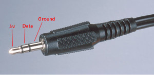
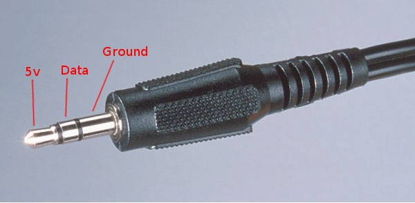
- Wire the miniplug to the waterproof DS18B20. The DS18B20 sensor has three wires:
Red: 5v -> Tip
White: Data -> Center Ring
Black: Ground -> Last Ring
By wiring it this way, the 5v rail is the last to connect, so you can unplug & reconnect the sensor while the controller is running (Note that the library will report -127F when it’s disconnected, so expect your heater to turn on).
- Build the monitoring shield. Use stacking headers in place of the provided headers, since this board will be sandwiched between our Arduino and the LCD screen. We use the prototyping space on the shield to support the headers for our sensors. Using bent-pin headers we can disconnect the external ports from the board to help troubleshoot and simplify final assembly.
Be sure you document the connections, however. These headers are not polarized, and you can toast your temp sensors if you connect them backwards.
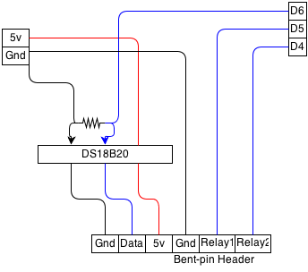
Wire the breadboard using the schematic below. We are using a 4.7k ohm resistor to “pull up” the OneWire network, and we will put a DS18B20 on the board to act as our ambient temperature sensor.
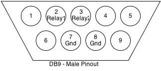
- Wire the DB9 connector. We picked a solder-cup type, so you can use regular pin headers. We only need 4 pins of the DB9 connector, so we will pick 2&3 and 7&8. Attach jumpers from these pins.
- Wire the Female Miniplug connector. We’re using a miniplug connector here because it’s tough and inexpensive. Make sure to match the pinout to your waterproof sensor from step 1.
- Wire your relay systems. Depending on what you choose for relays, this will differ. I used a serial cable from Jameco in my build because I had it lying around, but the very small gauge wire inside (20 or 24) is fragile, and needs support. Use one signal wire and one ground wire per relay. You can tie both signal wires together (feed both into the same relay), but note that if you select Mode 2 on the controller, you can get into a state where whatever is connected (heat or cooling) is always on.
Note: The Arduino doesn’t provide a very strong signal to the relay, and depending on how you wire the connections, you can create a path that has too much resistance. If you’re using a PowerSwitch Tail, you’ll know this is the problem because the LED will light, but the relay won’t fire. Shorten your serial cable to about 18 inches, and it will work.
- Assemble the LCD shield per Adafruit’s instructions: http://learn.adafruit.com/rgb-lcd-shield. There are no special instructions here, as it will be the top of our system.
- Stack your components together, paying attention to polarity when connecting the jumpers. Eventually you’ll want to put it into a nice enclosure, but for now, all of the parts are here.
Firmware
You will need to install a few libraries into your Arduino environment to build this project. If you’re not familiar with this process, see Adafruit for help.
- RTC Library:https://github.com/adafruit/RTClib/archive/master.zip
- SD Library for Mega: http://learn.adafruit.com/adafruit-data-logger-shield/for-the-mega-and-leonardo
- LCD Shield Library:https://github.com/adafruit/Adafruit-RGB-LCD-Shield-Library
- Fermtroller Sketch: fermtroller
Extract the fermtroller project into a new Arduino project folder, open, and compile!
Note: The fermtroller project does not include code to set the time/date on your RTC. You will need to load a sample project to do this before running fermtroller, or your logging timestamps will be off.
Operation
Connect all temperature sensors and relays before connecting power to the Arduino controller. After a few seconds of boot time, the controller will start. On power-up, the controller uses the following defaults:
- Min Temp: 67F
- Max Temp: 69F
- Fuzz: 0.25F
- Wet Therm: 1
- Mode: 0
The controller returns to these settings anytime power is lost, so you will want to check on your beer after a power failure.
Display
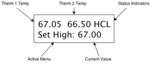
The display will show the temperature from both sensors, and a status on the top line. There are three flags that may appear in the status area:
- H – The Heater is running
- C – The Chiller is running
- L – Data is being logged to the SD card
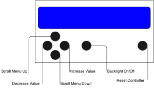
The second line of the display shows your current menu setting, and allows you to make changes. Use Up/Down to scroll through menu options, Right/Left to make changes. All changes are written to memory and effective immediately. Use the Select button turn the backlight on and off.
Menu Options
- Set High – Set the maximum temperature for the fermenter, in Degrees F
- Set Low – Set the minimum temperature, in Degrees F
- Set Fuzz – Set the Hysteresis level, in Degrees F (how much the temperature continues to change, even after the heater / chiller is shut off. This will vary depending on your heating/cooling system)
- Set Therm – Set which thermometer is used as the “wet” – the one in the beer
- Set Mode – Set the operational mode for the controller
0 – Heat only 1 – Chill only 2 – Heat and Chill
Future Plans
As I use my controller, I hope to add some more functionality.
- Ability to remove SD card while running
- Ability to store / read data from SD card for graceful recovery after power failure
- Ability to schedule temperature ramp up / down
- Set the correct write time on the SD card file (limitation of the library)
- Improve the efficiency of the code as to not require a Mega
Licensing
The hardware plans and software are free; you can redistribute it and/or modify it under the terms of the GNU General Public License as published by the Free Software Foundation; either version 2 of the License, or any later version.
This system is distributed in the hope that it will be useful, but WITHOUT ANY WARRANTY; without even the implied warranty of MERCHANTABILITY or FITNESS FOR A PARTICULAR PURPOSE. See the GNU General Public License for more details.
The GNU GPL can be found at: http://www.gnu.org/licenses/gpl.txt or write:
the Free Software Foundation, Inc.
59 Temple Place – Suite 330
Boston, MA 02111-1307, USA.
Nice! Will have to try this out.